Overview
A tapered rod string uses multiple rod sections of decreasing diameter from surface to pump. This distributes loads more efficiently than a straight string and is standard practice in most rod-pumped wells.
Getting the taper design right directly impacts rod fatigue life, peak polished rod load, and energy consumption. An under-designed upper section leads to premature failures. An over-designed string wastes money on unnecessary steel. PetroBench RodSim lets you model any taper configuration, evaluate stress distributions, and iterate quickly toward an optimal design.
Before You Start
You'll need the following information before building your rod string model:
- Total rod string length (surface to pump seating nipple)
- Rod grades available (e.g., Grade D, Grade K, high-strength alloys)
- Rod diameters to evaluate (common sizes: 3/4", 7/8", 1")
- Target pump size and expected fluid load
- Well deviation survey (if applicable)
Create a New Rod String
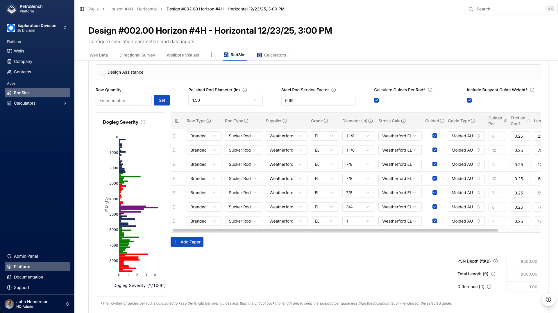
Open RodSim and navigate to the Rod Data tab. Click Add Rod String to create a new configuration. Give it a descriptive name - something like "Well 14-3 Taper 87-75-62" so you can identify the taper sizes at a glance.
The rod string editor starts with a single section by default. For a tapered string, you'll add additional sections to build out the full configuration from top to bottom.
Add Rod Sections
Click Add Section to add each taper segment. Sections are ordered from the top of the string (polished rod) to the bottom (pump end). For each section, configure the following four parameters:
Rod Grade
Select the rod grade from the dropdown. PetroBench includes standard API grades (C, D, K) as well as common proprietary high-strength grades. The grade determines the allowable stress range used in fatigue calculations. If you're mixing grades across sections - for example, a high-strength top section with standard grade lower sections - set each section independently.
Diameter
Choose the rod body diameter for this section. Standard API sizes are 5/8", 3/4", 7/8", 1", and 1-1/8". In a typical three-taper string, the largest diameter goes at the top where loads are highest, and smaller diameters run toward the pump.
Length
Enter the length of this section in feet. The sum of all section lengths must equal your total string length. RodSim validates this automatically and will flag a mismatch. When starting from scratch, API RP 11BR taper percentage tables provide a solid baseline for dividing string length across sections based on pump size and rod combination.
Guide Spacing
Set the rod guide spacing for each section. Guide spacing affects tubing wear and is especially important in deviated wells. PetroBench defaults to standard spacing but allows per-section overrides. In high-deviation intervals, tighter guide spacing reduces side loads on the tubing wall. You can adjust this per section to match your wellbore profile.
Review the Rod String Summary
After adding all sections, the rod string summary panel updates automatically. This shows:
- Total string length and weight
- Buoyant weight in fluid
- Stretch components (elastic, thermal, and overtravel)
- Stress at each taper transition point
- Modified Goodman fatigue diagram for each section
Pay close attention to the stress ratios at the top of each section. This is where failures occur. The Modified Goodman diagram shows each section plotted against its allowable stress envelope. All sections should fall within the safe operating region with adequate margin.
Compare Taper Configurations
RodSim supports side-by-side comparison of multiple rod string configurations. To compare different taper designs:
1. Build your baseline rod string using the steps above.
2. Duplicate the configuration to create a variant.
3. Modify section lengths, diameters, or grades in the variant.
4. Run the simulation for both configurations.
5. Open the comparison view to see results side by side.
The comparison view highlights differences in peak load, minimum load, stress ratios, and estimated fatigue life. This makes it easy to evaluate trade-offs between a lighter string with less safety margin and a heavier string with longer expected life.
Run the Simulation
Once your rod string is configured, run the full RodSim analysis. The simulation calculates dynamic loads using the wave equation, accounting for the material properties and geometry of each taper section individually. Results include the predicted surface dynamometer card, downhole pump card, and stress profiles along the entire string length.
Check the stress profile plot carefully. The stress should step down at each taper transition. If any section shows stress exceeding the allowable range for its grade, you need to either increase the diameter, upgrade the grade, or redistribute length between sections.
Practical Tips
Start with API RP 11BR. The recommended practice tables give you proven taper percentages for standard rod combinations and pump sizes. Use these as your starting point, then adjust based on your specific well conditions. There's no need to design from scratch when decades of field data have established reliable baselines.
Watch the transition points. The top of each smaller section carries the most stress in that segment. If you see a section with a stress ratio above 0.9 on the Goodman diagram, consider lengthening the section above it or bumping up the grade.
Consider rod weight. A heavier top section increases the polished rod load and the structural load on your pumping unit. If you're close to the unit's beam rating, a three-taper string with a shorter heavy top section may be better than a two-taper design.
Account for corrosion. In corrosive environments, de-rate the allowable stress or select a corrosion-resistant grade for the lower sections where CO2 and H2S concentrations are typically highest. PetroBench allows you to apply service factors per section to account for this.
Iterate quickly. The duplicate-and-modify workflow in RodSim is designed for rapid iteration. Build three or four candidate designs, compare them side by side, and pick the one that balances cost, fatigue life, and unit loading for your specific situation.
Common Taper Configurations
For reference, here are the most common rod combinations used in the field:
Two-taper: 7/8" x 3/4" or 1" x 7/8". Suitable for moderate-depth wells with standard fluid loads.
Three-taper: 1" x 7/8" x 3/4" or 7/8" x 3/4" x 5/8". The most common configuration for wells in the 4,000 to 8,000 ft range.
Four-taper: 1-1/8" x 1" x 7/8" x 3/4". Used in deep wells or high-load applications where additional load distribution is needed.
Each of these can be modeled in RodSim by adding the appropriate number of sections and configuring them as described above. The simulation handles all the physics regardless of how many taper sections you define.